In the Tank
A look at 240 Volvo in-tank fuel pump and fuel gauge sender issues.
These notes generally apply to 1979 through 1993 normally aspirated and turbo 240 wagons and sedans, taken from my family fleet experiences with the following:
79 244DL, 83 244DL, 83 242Ti, 83 244Ti, 84 244DL, 89 245GL, 89 244 GL, 90 244, 91 244DL, 91 244GL
Some earlier models (75-78) may have used different pumps or no tank pump at all, depending on retrofits Volvo offered. I have only book knowledge of those years, so this page may not be helpful. Volvo k-jet manual tank pump pages
Speaking of book knowledge… It never hurts to carefully read what the manufacturers said about their product. Volvo factory manuals (green books) describe the transfer (or tank) pump in Group 23. Removing/refitting the sender assembly is outlined in one paragraph of six sentences. Robert Bentley expands this Volvo information in its Volvo 240 Service Manual, Chapter 230. The Haynes series on 240 often treats us to photos of real (sometimes dirty and rusty) cars and evidence someone actually performed the steps indicated, in contrast with the factory literature which is often prepared before the first models even hit the showrooms. My late edition Haynes describes the pump replacement in Chapter 4 part A.
These
notes I’ve assembled are intended mainly to remind me of lessons learned in
personal auto maintenance as a hobby, and to the extent you may make use of
them, intended only for those already sufficiently skilled in safe vehicle
maintenance. This is no shortcut past
purchasing a repair manual. This is not a “step-by-step” tutorial. Working in the fuel system is not the next
skill level step after do-it-yourself oil changes and brake pads. Fuel is dangerous.
Revisions and Corrections
December 2010: Additional information on failure modes of aftermarket pumps,
sender, and seal, with images.
Correction to diagnostics of early 80's wiring.
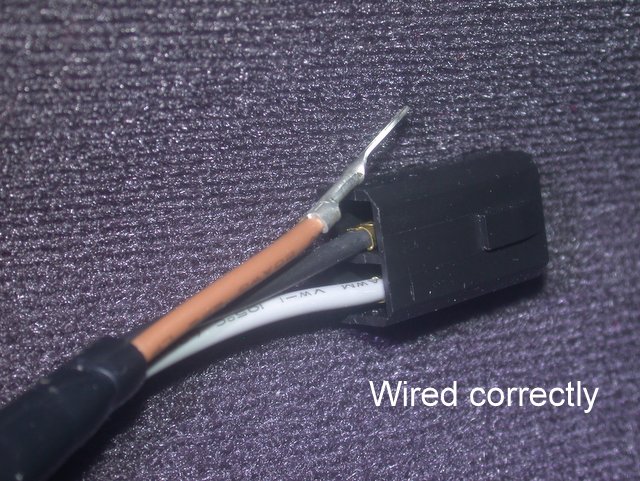
December 2015: Added pics of
correctly wired senders. Updated
experience with Airtex E8778. Added notes in verifying a running tank pump
in diagnostics.
September 2019: More on the Airtex E8778
Pump Diagnostics
Most of us recognize the tank pump can quit altogether without stopping the car. Its job is to lift fuel from the tank and feed it to the pressure pump, located under the car and in front of the fuel tank. Depending on the fuel level in the tank, the fuel temperature, and condition of the coupling hose in the tank, the main pump can suck the fuel without help, past a stalled tank pump. If the main pump is in good shape, the condition may go unnoticed for some time, but I believe this extra work burdens the main pump and causes heat and accelerated wear.
A hint is sometimes given by the noise the main pump makes when it is either starved for fuel input or electrical input. Instead of the smooth low pitch hum this positive displacement Bosch pump emits when all is well, a raucous buzzing noise warns it is trying to pump vapor along with the fuel.
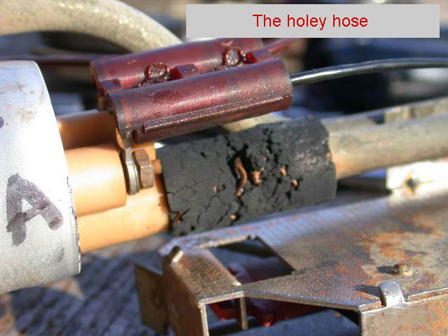
Another hint may be the correlation of driveability with fuel level. A full tank of cool gasoline may mask a dead tank pump. A common fuel level clue also results when the short hose that joins the tank pump with the fuel sender’s discharge pipe is leaky. When the fuel level uncovers the hose, air is drawn into the main pump.
A good starting point with any diagnosis is to check the power, or voltage, at the source. Because the fuse panel itself is a frequent home of poor connections, make the first measurement to the right-side terminal of the tank pump fuse – to be sure any voltage drops through the several connectors, fuses, and fuel injection relay, are not significant. Expect 13 to 14 volts with the motor running.
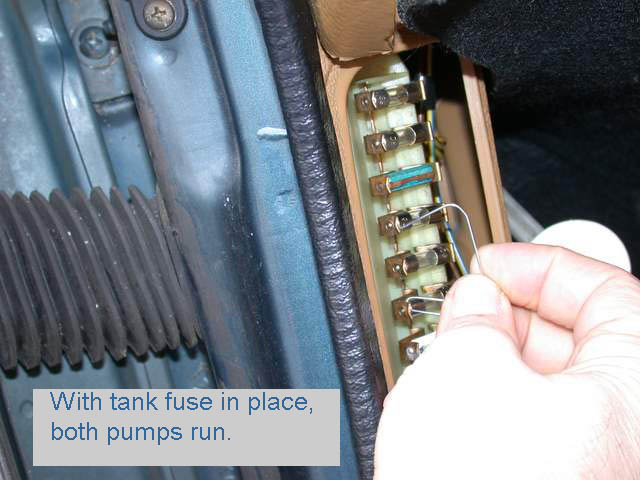
To test the pump itself, plus the sender wiring, apply
battery power (in this example, from fuse #6) to the load side of the tank pump
fuse. This is fuse #4 in 85-93 models,
or fuse #5 on the earlier cars or 85 Turbo.
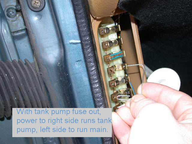
Beginning in 89, the oxygen sensor heater is also powered here. If the fuse is removed, you’ll power up the
tank pump on the right-hand terminal, and the main pump on the left. Test the pump a number of times to be sure it
starts with each try, and the brushes don’t wind up in a bad spot on the
commutator. Feed
pumps in 78 and earlier models are not separately fused.
If you can’t hear the tank pump in a quiet environment, it probably is not working. A helper can try listening at the filler neck with the gas cap off, but this can be a difficult call if on the side of a busy highway. If still not sure, the tiny spark made by connecting the power at the fuse should* be an indication the pump is responding. A test light in series will indicate current too, but remember to disconnect the oxygen sensor heater (89-93) if resorting to this method. To fully rule out the tank pump, you must be able to hear the pump to make certain it runs smoothly and evenly.
*Since writing that, I have come
across a pump which did draw some current, and hence the tiny spark, but did
not make a sound. It was stuck. One very short brush had cocked in the holder
and jammed against the edge of a commutator segment. You need to hear the pump running for a
confirmation.
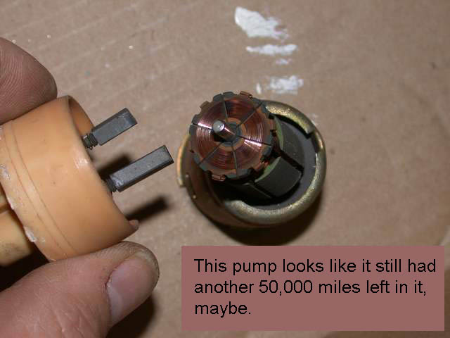
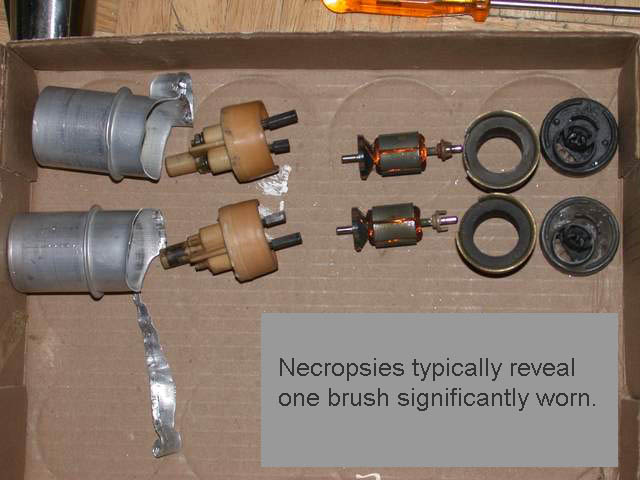
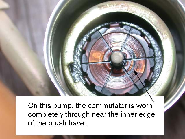
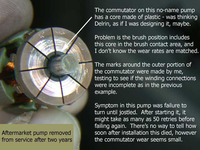
Here’s a look at a tank pump in pursuit of the root cause of its failure. It is always risky to assume, the few cases one has analyzed, correctly represents the majority of cases. But those few show a trend, in my experience. The trend is one short brush, resulting in weaker spring pressure on the commutator. The process seems to be the pump stops on a bad spot, with the short brush making poor contact. Or, it runs, but unevenly and fitfully, building vapor embolisms that make the main pump cry out in pain. High resistance at the point of contact results in heat – that appears to show up as darkened areas on the commutator surface Or the commutator may be completely worn through, and the dark area is the black plastic behind it. If the pump is physically bumped, it may resume, until next it stops on a contaminated part of the commutator.
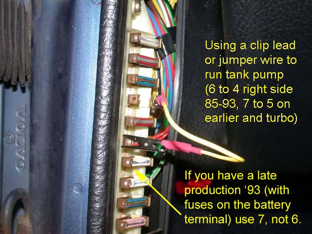
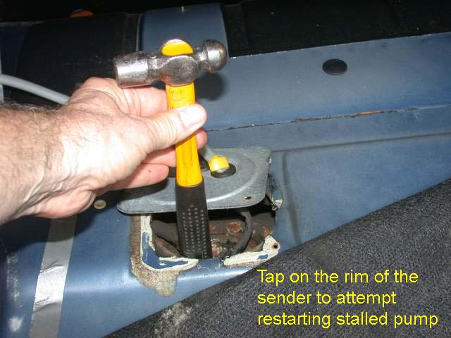
What better way to convict the pump itself, than to power it with a jumper, as above, and rap on the sender top (or maybe even on the tank bottom) and hear it take off running again.
Sender Diagnostics
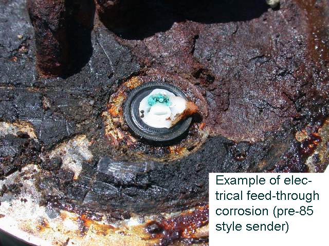
The “sender” actually refers to the variable resistor operated by the float in the fuel tank, which sends the level information to the gauge. But, I think we use the term to identify the entire contraption mounted at the top of the tank, holding the float assembly and the lift pump inside the tank. It is an expensive part that rusts. Part of the rusting process opens up the hermetic seal protecting the electrical feed-through of the wiring for the gauge and tank pump. Once water gets in, electrolysis speeds the corrosion of the powered circuits and eventually breaks the path to the gauge or pump.
To troubleshoot a faulty fuel gauge, with ignition in key position II, use a test light at the sender wire. It is gray on all models. Connect it from ground to the gray wire by back probing the connector. If using an incandescent test lamp rather than an LED type, the fuel gauge will indicate some level, if the sender was faulty and always reading empty before.
If using a meter, disconnect the plug and measure at the gray wire going into the main harness, and you will measure the 10 volt stable gauge supply (except on the earliest models using a thermal stabilizer, where the voltage will fluctuate). The factory service manual suggests substituting a 68 ohm resistor to check the gauge reads approximately 2/3 full, but a sender problem is rarely one of inaccuracy, it’s just inoperative or intermittent.
The picture below shows a wagon with the storage compartment removed to reveal the tank sender access cover. A plastic cover protects this in the sedan trunk.
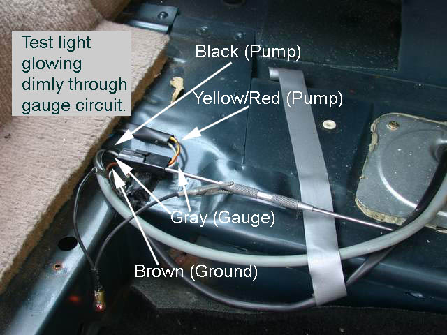
Here’s what lies below the access panel –
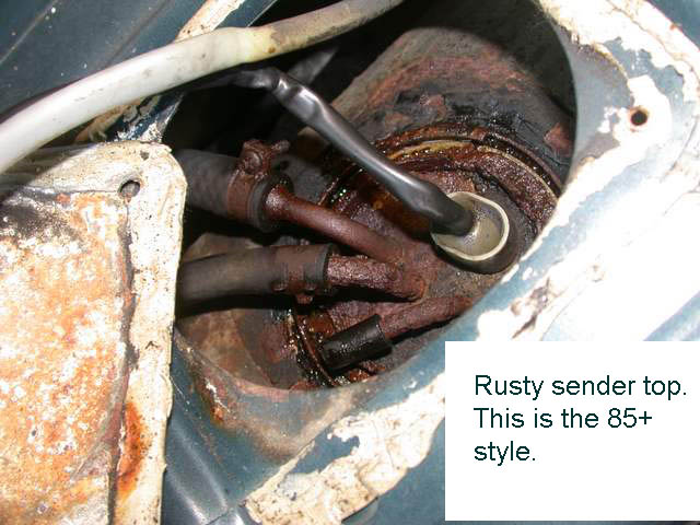
And what can happen under the sealed electrical feed-through.
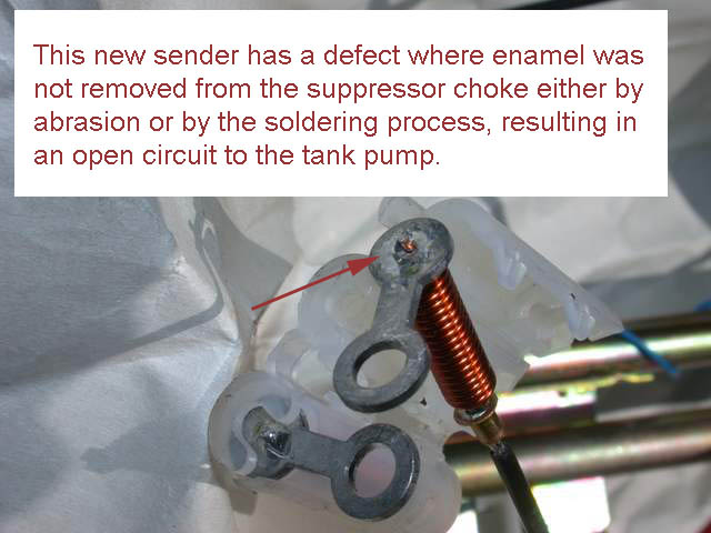
Sometimes new senders need diagnosis too. The genuine Volvo part lists for something north of $200 but with discounts can be found for much less. The original was made by VDO (think gauges and speedometers), but if you decide to go low ball, and buy the made in Taiwan copy as I have several times (around $100) , be prepared to deal with a few quality problems I and others have found:
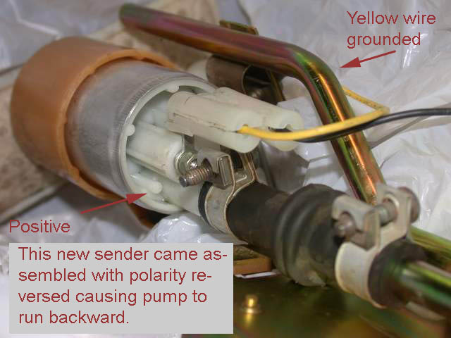
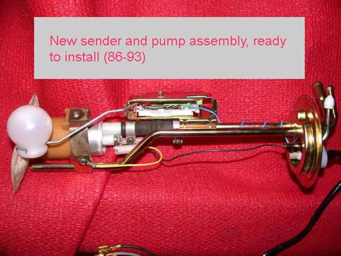
Check yours. Looking at the next photo, note the motor lugs are facing toward the camera. The black wire needs to be at the bottom instead of at the top. Looking closely at the white plastic holder, you'll even see "+" and "—" molded in. The yellow ground wire must go to "—" and the black to "+".
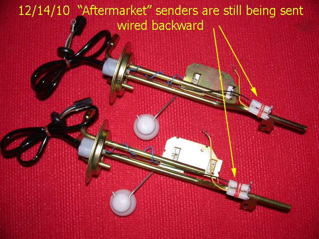
Hydlide on brickboard says they are getting it right now, as of Dec. 2015.
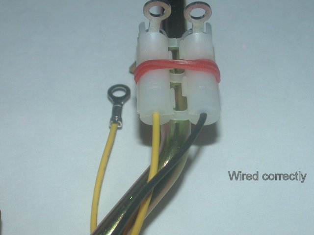
Of course, you’ll be smarter than I was and check for, and correct, these minor defects before installing into the tank.
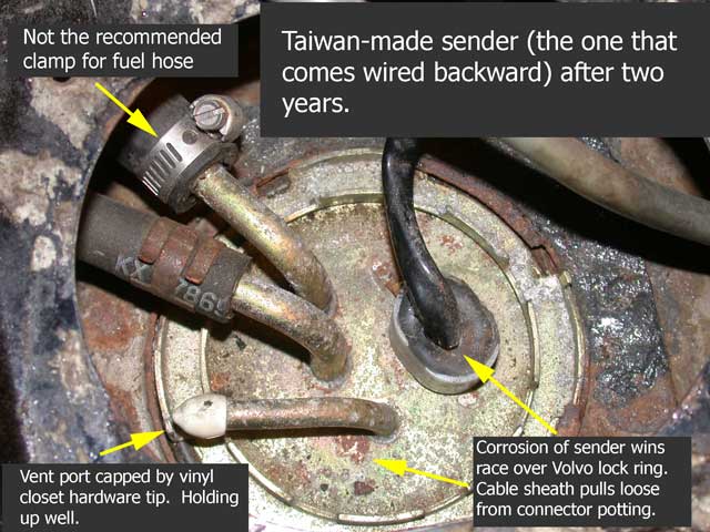
Here's a look at the sender shown
above after two years of experience:

Aftermarket pumps
Speaking of checking aftermarket parts… I’ve followed the Volvo maintenance and repair forum Brickboard RWD for some 10 years and heard many complaints from DIY and shade tree mechanics receiving poor quality parts. Most everyone wants to learn how to identify a good part, by brand name, country of origin, or supplier. It only stands to reason we will be skeptical of the goodness of a part we can get for $40 “aftermarket” which lists for $143 at the dealer.
I expect most repairs to these cars are being made by shops for folks who expect to get maybe one or two more years from the old car, and those of us researching the best parts are a small minority. The market follows the majority, who need a cheap part, not a good part. We expect if we buy the part from Volvo, it will be the best – after all, Volvo would waste money if its dealership techs charged warrantee work re-replacing shoddy parts. However, dealerships themselves are not doing that many 240 repairs any more, so I wonder if Volvo has any incentive to insist on the best quality from their parts suppliers and test (incoming inspection) to maintain it, when it comes to keeping our rear-wheel drive cars on the road.
Specifically, with the tank pump, I’ve followed several stories where the job was done multiple times due to receiving DOA pumps. In one case the repeated failures were pumps purchased at the Volvo parts counter. Of course, I understand something about shade tree mechanics and DIY enthusiasts – we don’t always install parts correctly, or diagnose their problems well. I know many parts quality complaints are truly problems with installation. Still, there are not that many ways to mess up this job.
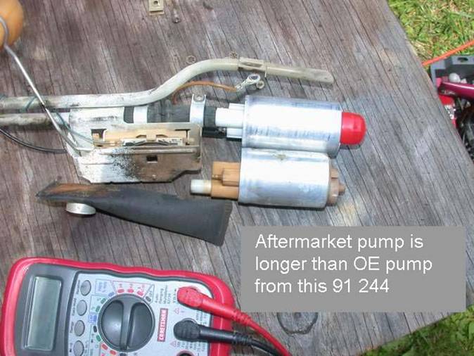
During my most recent pump replacement, using the $40 aftermarket unit, I used an ohmmeter to check my work after completing the pump swap and before putting it back in the tank. The meter gave me a high reading between brown and black (pump) wires. I expect a few ohms, but it reported something over 600 and moving the probes to the pump terminals did not improve things. I was dismayed, because the pump I used was purchased a long time ago, languishing on my parts shelf, waiting to be needed. I’d be expecting a lot of my supplier to take it back at this late date.
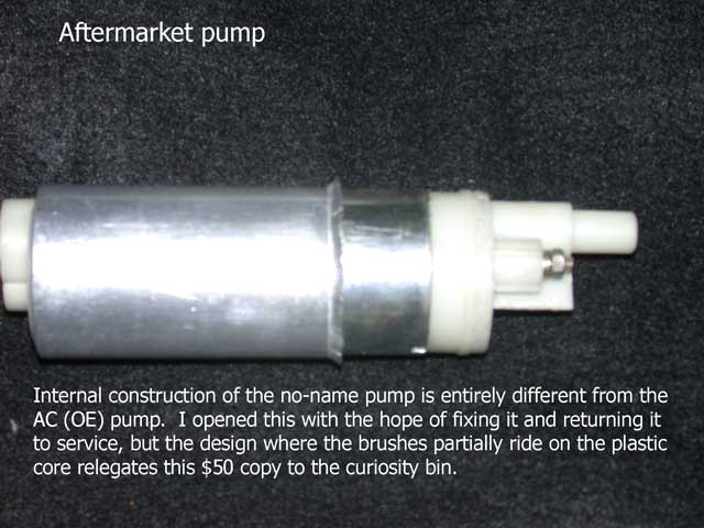
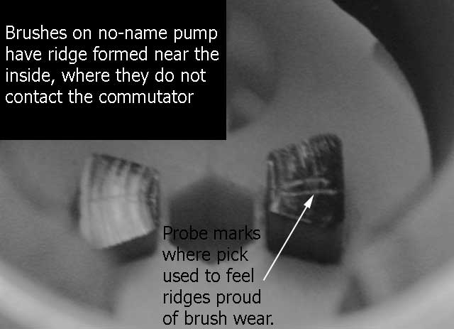
I brought the dead pump to the workbench, to verify by applying power, and resigned myself to peeling open the can to maybe learn why the $40 pumps are not the right ones to buy. Surely, I could get it going by nudging the impeller through the intake opening. I could view the outer portion of the commutator through the outlet port, seeing what appeared as discoloration on about 10% of it. It would run maybe twice before needing a nudge, so I decided to see if I could “wear in” the brushes.
Running the pump dry can’t be any good for it. The impeller and its chamber are of plastic; they need some kind of lube in the absence of fuel.. I ran it for a few seconds, watching the current increase with time. I kept it up anyway, thinking I’d have a challenge opening and closing the can if it came to that, so when it ceased needing a nudge to get it started, I was glad to put it in the car.
Update: Not long after installing this pump, I found it again not working
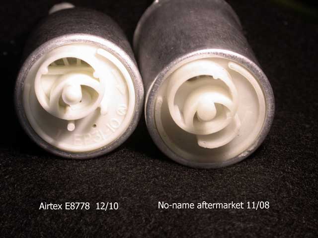
Taking the no-name "aftermarket" pump apart revealed the original problem.
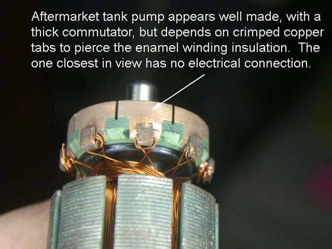
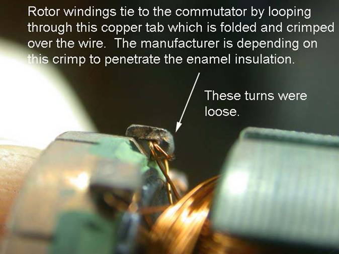
In Dec. '09 I said it appeared to be well made, but now, in Dec. '10, I've had to change another of these same "aftermarket" $40 pumps, and I have no way of knowing how long it actually ran, after installing it in Nov. '08. After finding the loose crimp in the first one, I carefully opened this one with the hope I might fix it and return it to service.
Airtex E8778
I replaced it with this pump, purchased locally for about $45.
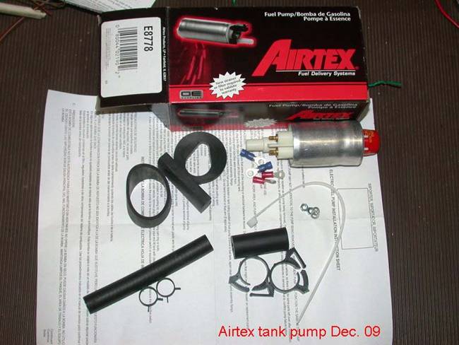
This Airtex E8778 is, as of Dec. 2015 (and still as of Sept. 2019), my choice of tank pump. All I have installed are still working, as I have incorporated the testing of the pump into the oil change routine in order to know that.
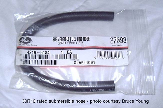
But you see the accessories that are included in the box? The only items I've used from there are the nuts and lock washers for the pump terminals. Don't assume Airtex sent you hose that is fuel resistant submerged in the tank. They didn't. Just throw the extra pieces in your junk box.
Sept. 2019: The Airtex E8778 choice (gamble) made in '09 seems to have worked well. I'm not going to delude myself to think a brand name means much in the rapidly changing world of aftermarket auto parts. However, 10 years without a problem beats all the experience I got with everything else. Quality in a brand can vary from one month to the next for a myriad of reasons.
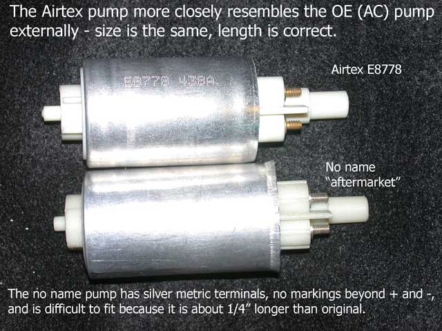
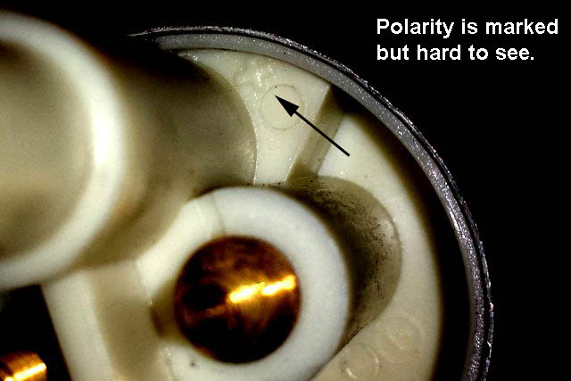
One problem I have encountered is hearing from others who have chosen the pump, saying it isn't marked for polarity. Today I pulled the spare from the shelf (purchased in 2015) and had a look. The polarity is there, cast into the end, but I admit easy to miss.
Another thing comes up often: the notion that the pump will pump backward (suck from the wrong end?) if the polarity is reversed. Not so. It is a centrifugal pump. Granted it won't be as efficient and it could wear out quickly if the polarity isn't observed, but I'm fairly certain you won't notice it in performance right away. After all, how long did it take you to notice the pump wasn't working at all?
Conclusion: Check the pump before dropping it in the tank. I don’t believe it will hurt it to give it a few quick half-second tests with power applied without fuel, and you might save yourself the effort of pulling it again, like I did-- twice.
Prep for repairs
Once you’ve determined to go “in the tank”, prepare for a few pitfalls.
Pitfall number one has to be dropping the tank. There is no need or advantage gained -- only pain and grief. All access is through the top.
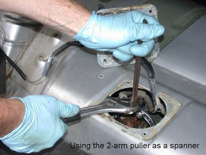
The first challenge will be removing the sender lock nut, so have the tools you intend to use before starting. The first time I changed a pump, I did not prepare. Like most of us, I just dived in. I looked around the shop for something to substitute for a brass drift to knock the nut around, but found nothing suitable. By chance, I found this old Craftsman gear puller fit the nut’s notches, and have used it ever since.
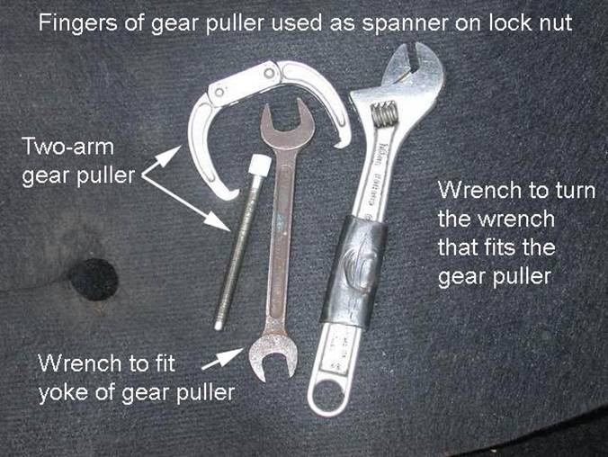
You probably won’t have this 2-arm puller. You can use a brass drift, I guess, or buy a purpose-made “bung nut tool” many have claimed saved their bacon. Volvo has a special wrench too -- #5169. Whatever method you decide on, the objective is to generate no sparks.
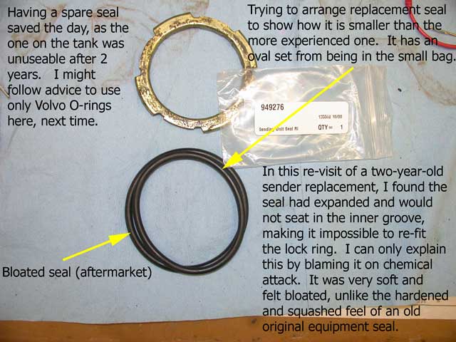
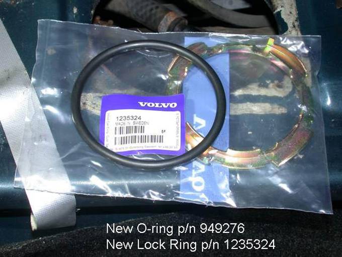
For less than $10 you can replace the lock ring and seal. The seal, I'm thinking, may be an item you want to get from Volvo. p/n 949276 is currently $4.02 MSRP – probably less than the aftermarket suppliers charge if you get any kind of discount, and after this month's experience, noted farther down on the page, may be worth the trouble.
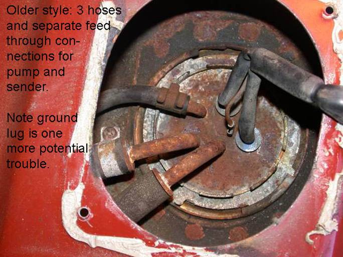
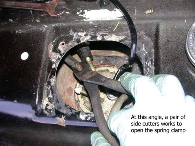
The next pitfall has to do with hoses. The sender will have a large output hose between it and the main pump, a smaller return hose, bringing the fuel back from the fuel pressure regulator under the hood, and possibly a third vent hose, if your k-jet car still has its original accumulator.
The large hose, 12mm inside diameter, based on others’
experience is hard to find. So if you
expect to need it for any reason, locate one in advance. So far I have not needed one, so I can’t help
much on where to get it, and likely would wind up pulling it from a parts car
in the junkyard. Volvo parts lists 79-85
designate part number 1266500, and in the 88-93 lists, I find 1312257, if I am
reading the parts list correctly. Recently I have heard on the boards 7/16" ID fuel hose
may be available from local suppliers if you ask. I am still unable to find either a definite
Volvo parts list ID (or aftermarket source) for the 19mm or 3/4" FI band
clamp shown in the photo below.
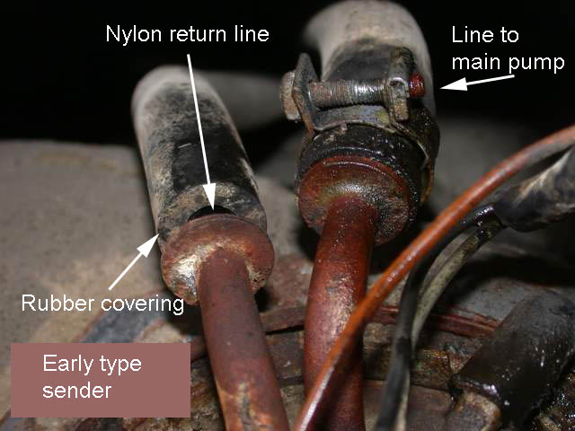
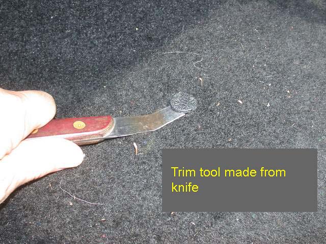
The return hose, on the early cars, is rubber covered nylon. The nylon is mated to the sender’s inlet barbed fitting using a heat process, and the rubber covering protects the nylon. This hose extends to a junction with the steel return line just above the rear axle.
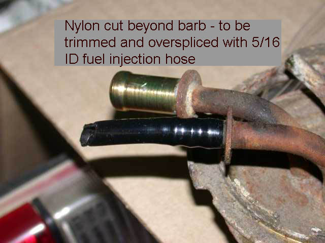
I believe the 5/16 ID injection hose fits better to this barb if the nylon is left in place. Removing the nylon creates a looser fit, and then any nicks in the barb, left by a knife, may start a leak.
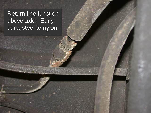
This junction reminds me of the phrase “pick your battles” where rust is likely to be found.
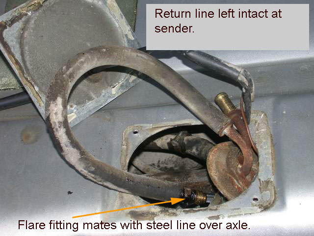
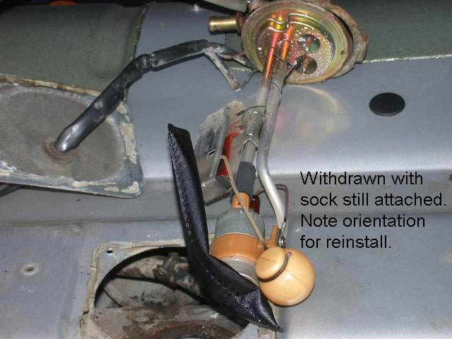
The nylon hose can sometimes be disconnected at the
over-axle junction and withdrawn with the sender, through the access hole. Be prepared to replace it entirely, though,
if attempting the disconnect leaves you with a rusty
steel line with its flare nut twisted off.
The nylon does seem sturdy enough to support a short splice, using 30R9
hose and fuel-type band clamps, but I have not tried
this myself. Some prefer to leave
that over-axle joint unmolested, and just cut the nylon immediately behind the
barbed fitting, and then re-join it with a short length of 30R9 and the
appropriate clamps. Alternately, a longer section of fuel hose can replace the
entire nylon line, from barb to barb.
5/16" ID line would fit best with the nylon left over the barb and
this would also remove the danger of nicking the barbs trying to remove the
hard plastic.
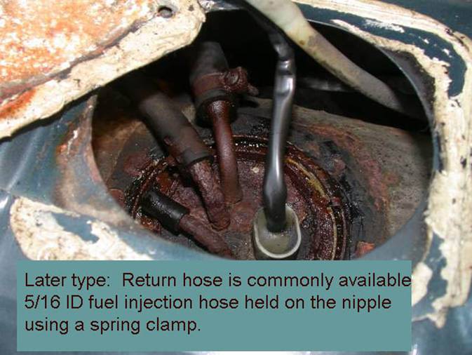
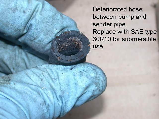
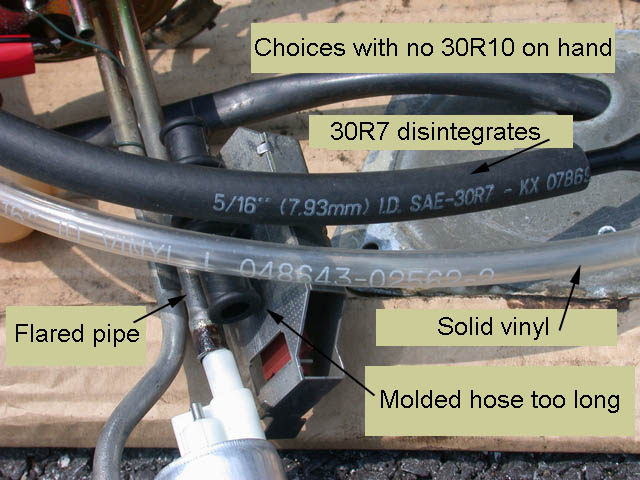
On the later cars, this hose is ordinary 5/16 (8mm) fuel hose, probably grade 30R7, but we’re more likely to find the more expensive 30R9 fuel injection hose in the store.
Your early 240 may have the third hose (in mine it leads to the fuel accumulator’s vent), or it is capped.
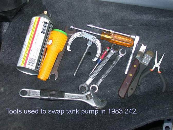
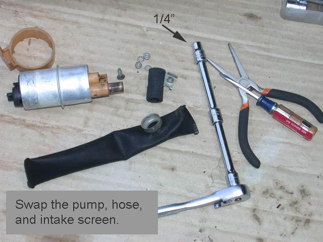
After changing a pump in an 83, I collected the tools left out to show how few are really needed.
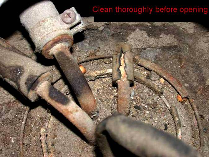
Before opening the tank!
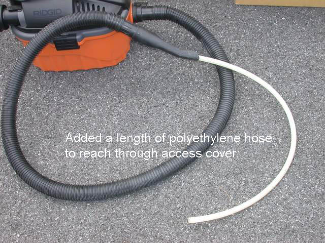
Before operating a vacuum cleaner near a fuel tank, use your nose. Make sure there’s no leaking fuel or fuel vapor that could be drawn into the vacuum cleaner motor. Do this before opening any fuel lines!
In case you just topped off the tank to see if that would make the car run better, be careful. Fuel in the tank is not usually a problem, but if there’s so much the filler pipe has fuel in it, it is likely to overflow when you loosen the nut. Bentley suggests no more than ¾ full before you begin.
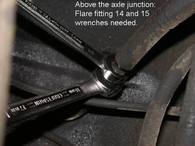
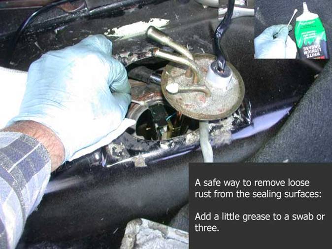
The brush and vacuum get used to remove as much loose dirt and scale as possible, from the area on top of the tank, so that none falls into it. Then some penetrating oil may help when loosening the bung nut. Also seen here are the line wrenches for the return line junction, and that puller I used as a spanner for the bung nut.
In the tank
The hoses need to be disconnected
before completely unlocking the ring.
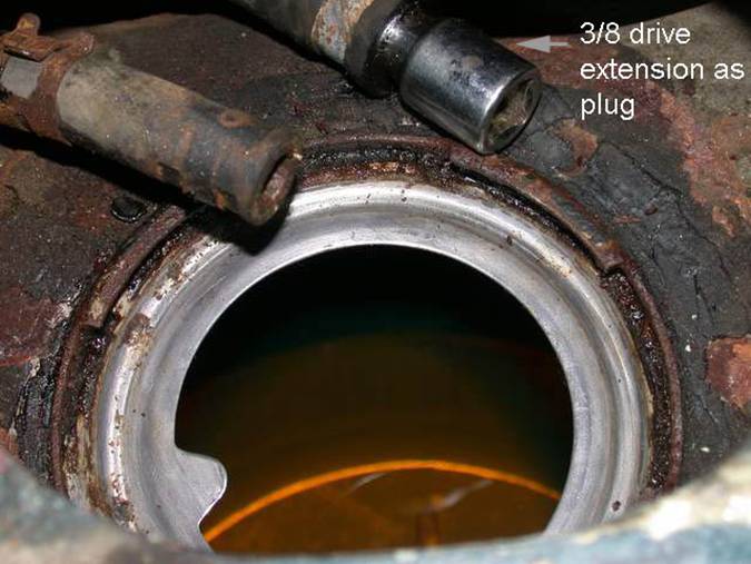
Once all the hoses and wiring are disconnected, I found it helpful to put a cork in the open lines. A 1/4" drive extension will fit the later version rubber return hose.
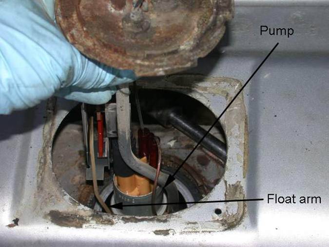
The first obstruction encountered is the frame around the gauge sender (variable resistor).
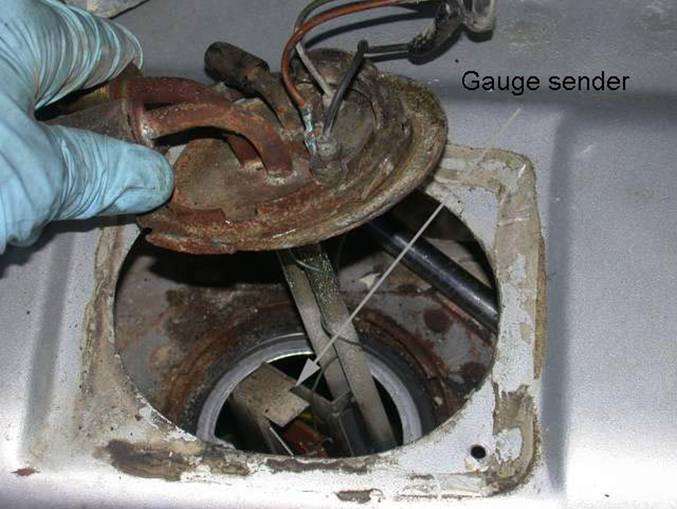
Next, the pump is withdrawn. Use patience here; you don’t want to go chasing the float ball around the tank.
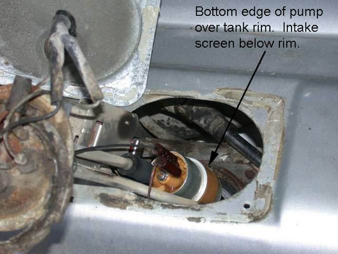
The tricky part is getting the float ball past the rim, while the intake filter sock catches any upward movement. It will fit through if the rim is between the pump’s bottom and the sock’s top.
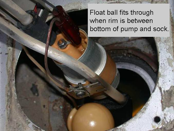
I try hard not to knock my socks off.
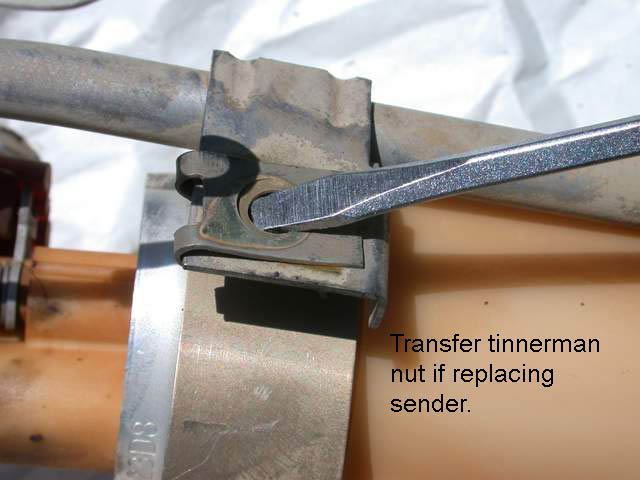
Repairs
Install the pump on the bench.
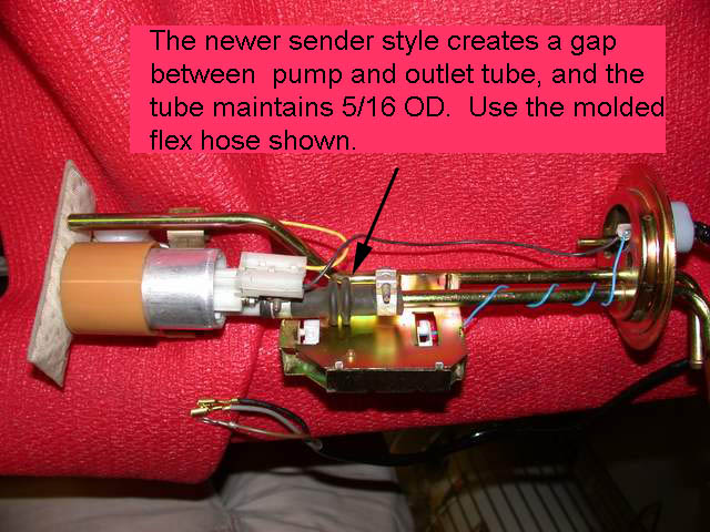
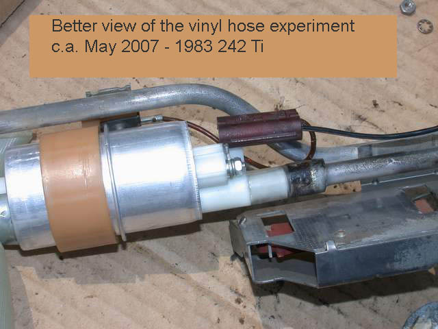
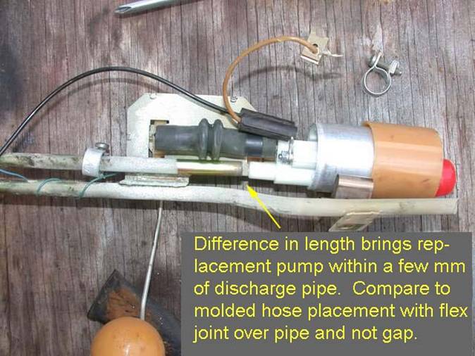
You might get the molded hose to fit, but the hose is too long and slips off the flared section to make a loose fit on the pipe. It is definitely not the correct application. Also, I haven’t been able to find the molded hose in any parts supplier listings of late.
Also note the lack of a barbed
connection for the fuel return on the senders used with rubber return
lines. These and the replacement senders
will need to have the nylon changed (or adapted) to the 5/16" clamped hose
fitting.
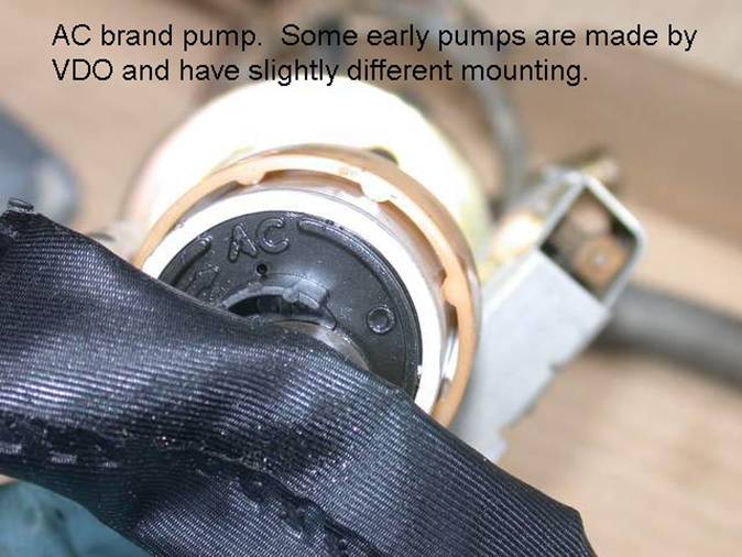
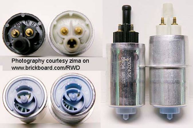
Here’s a comparison of two new AC brand pumps purchased by zima on www.brickboard.com/RWD. The one with the flange matches those in the earlier style senders and came packed in GP Sorensen wrapping (available at chain retailers Advanced Auto, O’Reilly, etc.) and the newer style (left) came packed in a genuine Volvo wrapper, but both obviously produced by the same manufacturer, AC Delco.
Back together
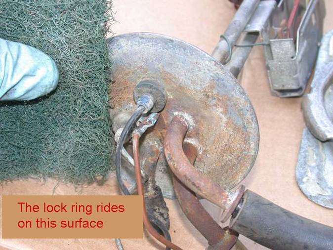
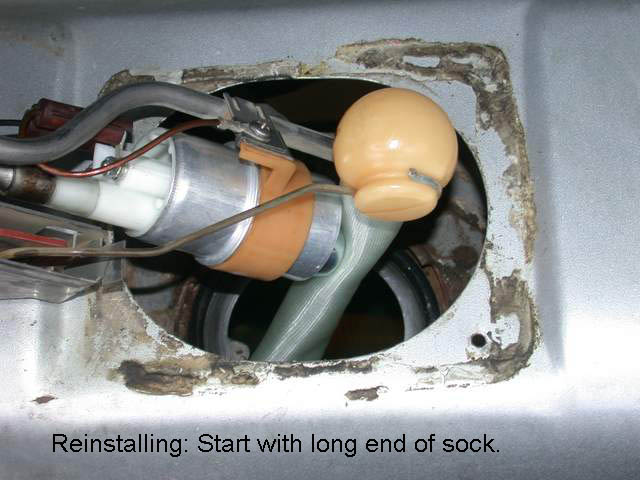
Some tips on putting it back together: First fit the long end of the sock, hook the short end under the lip, and then squeeze the float ball through, with the pump inlet against the lip. Notice the key in the rim mates with the locating indent in the sender. Bentley says to coat the O-ring with petroleum jelly, however the locking ring glides on the top of the sender..
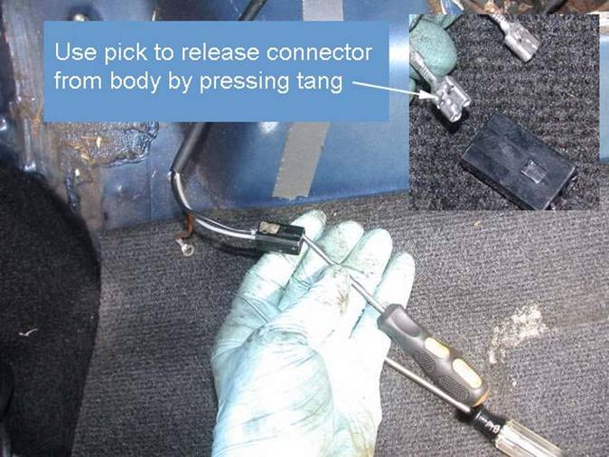
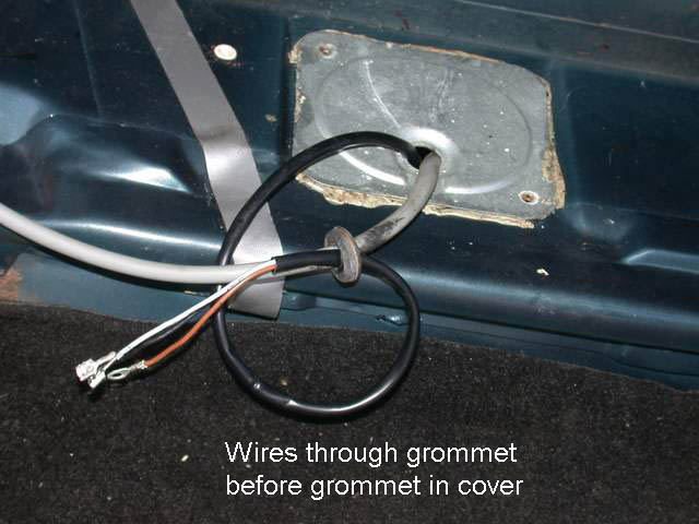
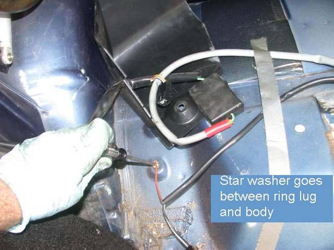
Connect the hoses and pay careful attention to the wiring. Insert the gray and black wires into the connector housing until they click, and see that the gray mates up with the car’s harness gray wire, and the black mates with the yellow/red. If you get it wrong, it could take days for you to notice the gauge doesn’t drop and a cool load of fuel may just pass by that inoperative new pump, so check the wiring, and test the pump just as you did to diagnose the problem in the first place.
Volvo k-jet manual tank pump pages