240 Volvo Temperature Compensation Circuit
Here is a quick path to the truth in temperature.
Temp Faker removal:
Work safe. Make sure you have your anti-theft radio codes, if any, and disconnect the negative battery cable.
Remove the headlight and dimmer knobs. Remove the plastic panels to the left and to the right of the cluster.
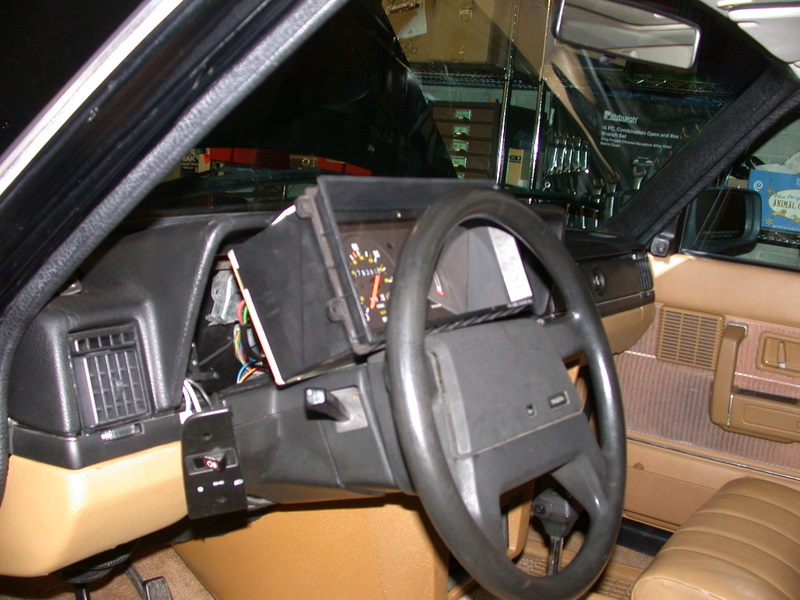
Four screws hold the cluster into the dash.

Set the cluster on the steering column.
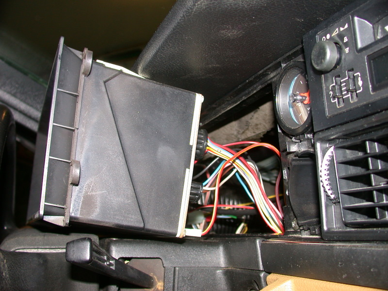
Make careful notes where all the wires and plugs connect. Don't trust this to your memory before disconnecting them.
(note: quite a number of us ignore this basic advice and wind up destroying the speedometer by plugging a seemingly orphaned white/red tachometer wire where it does not belong!)
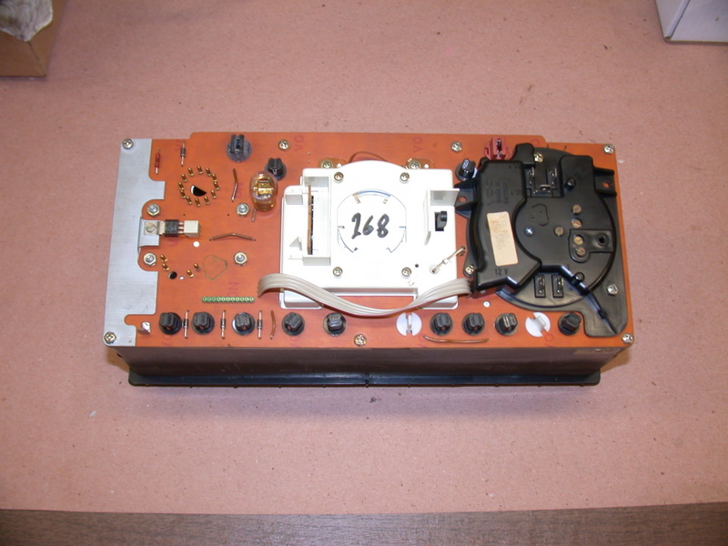
Lay the cluster face down on a clean surface. There are two paths you can take now. You can do this without going inside the instrument panel with nothing but a scrap of yellow wire and some crimp terminals. Or go into the panel. Both ways will accomplish the same end, but you may want to skip the disassembly by making one small modification to the wiring harness.
External Wiring Method
Bypass the round 12 pin plug and the compensator board by going directly from the sender wire to the gauge terminal:
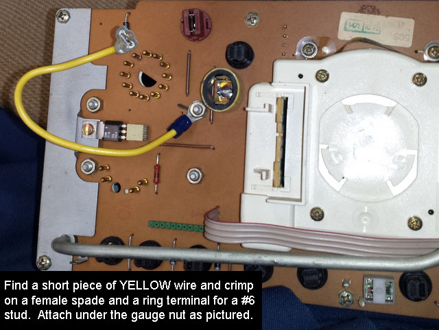
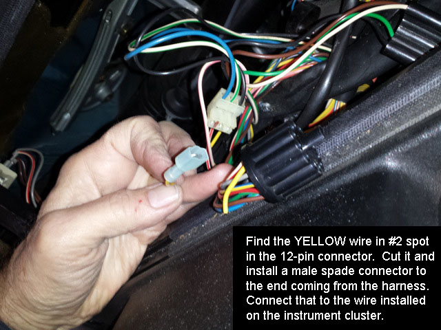
Remember to plug the yellow wires together when reinstalling the cluster, and remember above all, if you don't have a tachometer, leave that stray white/red wire you found back there loose, and that's all there's to it.
Internal Bypass Method
Modifying the cluster might be preferable if, during the car's life, you anticipate swapping instrument panels again.
Remove the 7 screws around its perimeter to separate the circuit board.


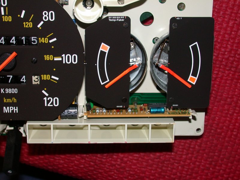
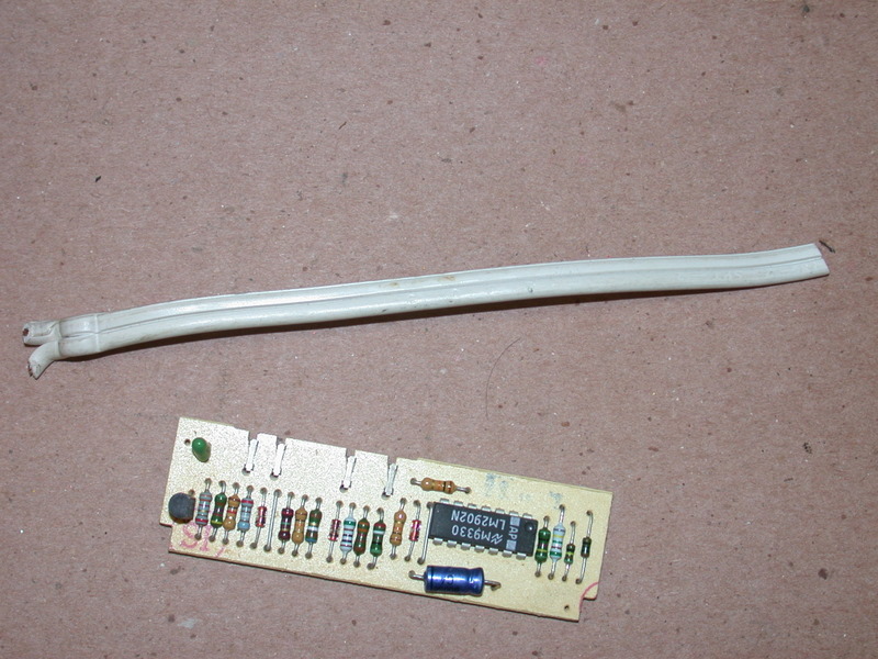
Under the temp and fuel gauges is a small daughter card. This is the temperature gauge stabilizer board. Pull it straight out. The board functions to reduce warranty (ha!) service by classifying varying temperatures, as sensed by the thermistor in the head, into three ranges of the gauge. It turns the gauge into an idiot light with roughly four states: cold, cool, normal, and hot.

But the add-on "afterthought" board didn't have room for decent connectors, so those tiny Berg sticks that it uses to make contact become weak and worn with vibration, moisture, and temperature extremes under the dash.
There are several options at this point. A replacement board could be installed, which would renew the female portion of the connection problems. The contacts might be painstakingly cleaned and retensioned. The board could be soldered directly to the pins. Or the board could be tossed in the trash can and replaced with a jumper from input to output, re-establishing the original analog temperature gauge as cars before 1986 were equipped.
Several options to jumper it too, depending on what's handy for you. A jumper can be soldered between pins 1 and 3, or wire-wrapped, or you could employ modern "insulation displacement" techniques (suggested by Svenĺs Maintainer) with a piece of lamp cord.

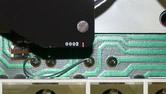
Wire wrap used here
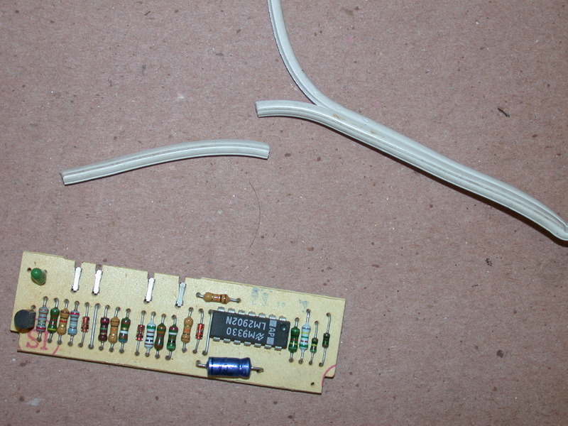
Sven's Maintainer's method: Push the unstripped ends of the lamp cord over the sharp Berg sticks. Genius.

When done jumpering, a continuity test can be made before assembling the cluster back into the dashboard. The photo below illustrates where to connect an ohmmeter, or continuity buzzer, to test between the gauge terminal and the cluster's pin leading to the temperature sensor on the head.

When communicating the needle position on the gauge...

index page