91 240 03/27/03 155000 mi. (rev. 09/17/05
– added photo of flex circuit fuse and notes about 2115 pins) (rev. 01/08/07 correction to power distribution in schematic)
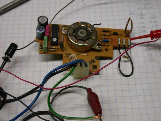
The 91 speedo driver board is laid out differently than the 89. Also notice wire color codes changed.
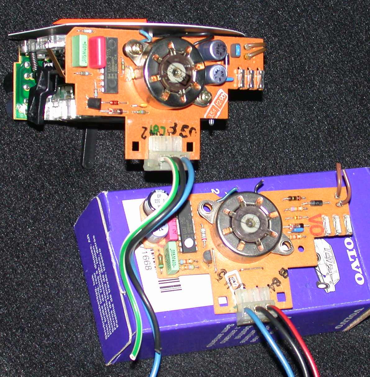
The 91 is assembled; the 89 is the loose board in front.
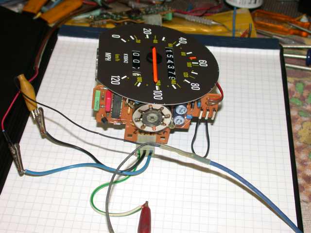
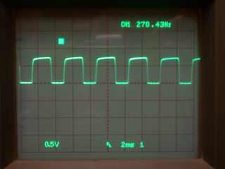
Connect 12V source and use jumper in place of flex circuit fuse. Connect sine
wave source. Threshold signal needed is about 150 mV rms,
all readings taken with 250 mV in.
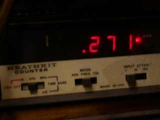
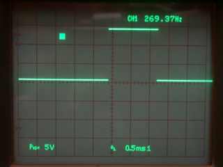
K10042 speedo reads 100 MPH with 271 Hz input. I
counted 160 steps taken by the odometer motor per mile. If 10042 represents the
counts per mile (Thanks Rob!) 100 MPH ought to correspond to
10042*100/3600=279, and the 2115 IC should be dividing the input signal
frequency by 10042/160=63 for the step rate. Someone can count gear teeth to
come up with the correct numbers...
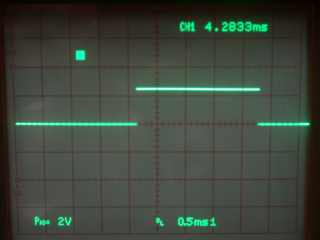
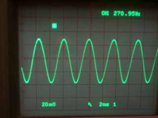
The limiter transistor collector. The second signal is
at pin 7. This appears to be part of the speedometer's phase comparator; the
duty cycle is a function of input frequency. At 88 MPH (shown) it looks like
50%. The 2.5V level is always 2.15 mS.
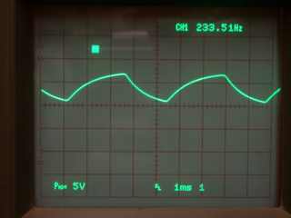
The input (pin 12) after integration. Pin 11 appears
to be the RC constant for the speedo function.
Precision parts and the ramp waveform cause me to believe this.
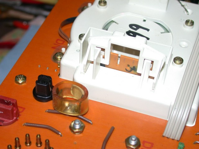
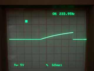
Pin 3 supplies an open collector vehicle speed signal to the ECU. The waveform
is shown using a 10K ohm pullup resistor. Above, right, is the flex circuit fuse, just
visible top and left of the white plastic gauge housing, where in the
foreground the card edge connector is visible along with the locking
tamper-evident clip.
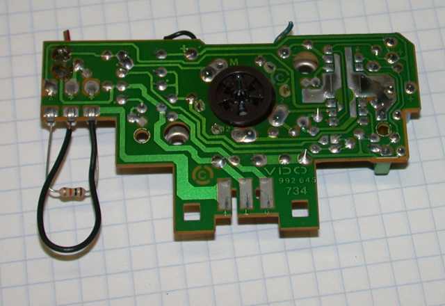
I was a bit surprised to find the odometer motor steps quite nicely without the
bearing and gear.
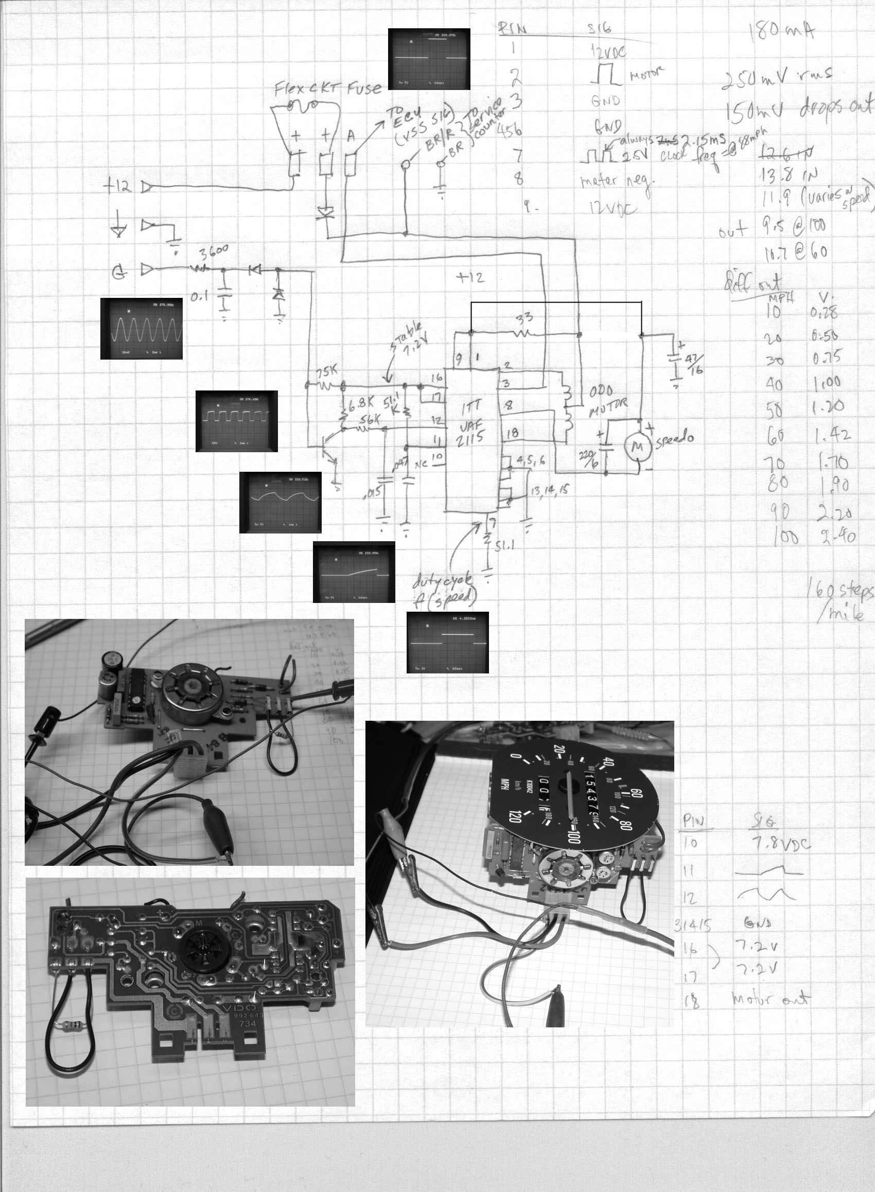
The notes on the right side of the page show the approximate voltage across the
speedometer movement coil at speed increments. The voltage is best measured
across the movement because the power consumption varies over the speed range.
There is significant stepper switching ripple at the power source beyond the 33
ohm resistor despite the 47 microfarad decoupler. (rev. An error in
tracing the power distribution led me to that conclusion about the ripple, but
I see now in the corrected drawing, the stepper is provided raw power ahead of
the decoupled portion of the circuit.) Average current used by the circuit is about
180mA. Note,
the pin numbers on the ITT 2115 are my own designations according to the