Connecting your Keyless Entry product to the 240
Whatever your choice of unit is, the instructions for it will be used to plan your connections. So far, those I've connected use the minimum of features; no trunk control, no panic horn, etc. Yes, I did add a remote starter to one 240, but that is another topic.
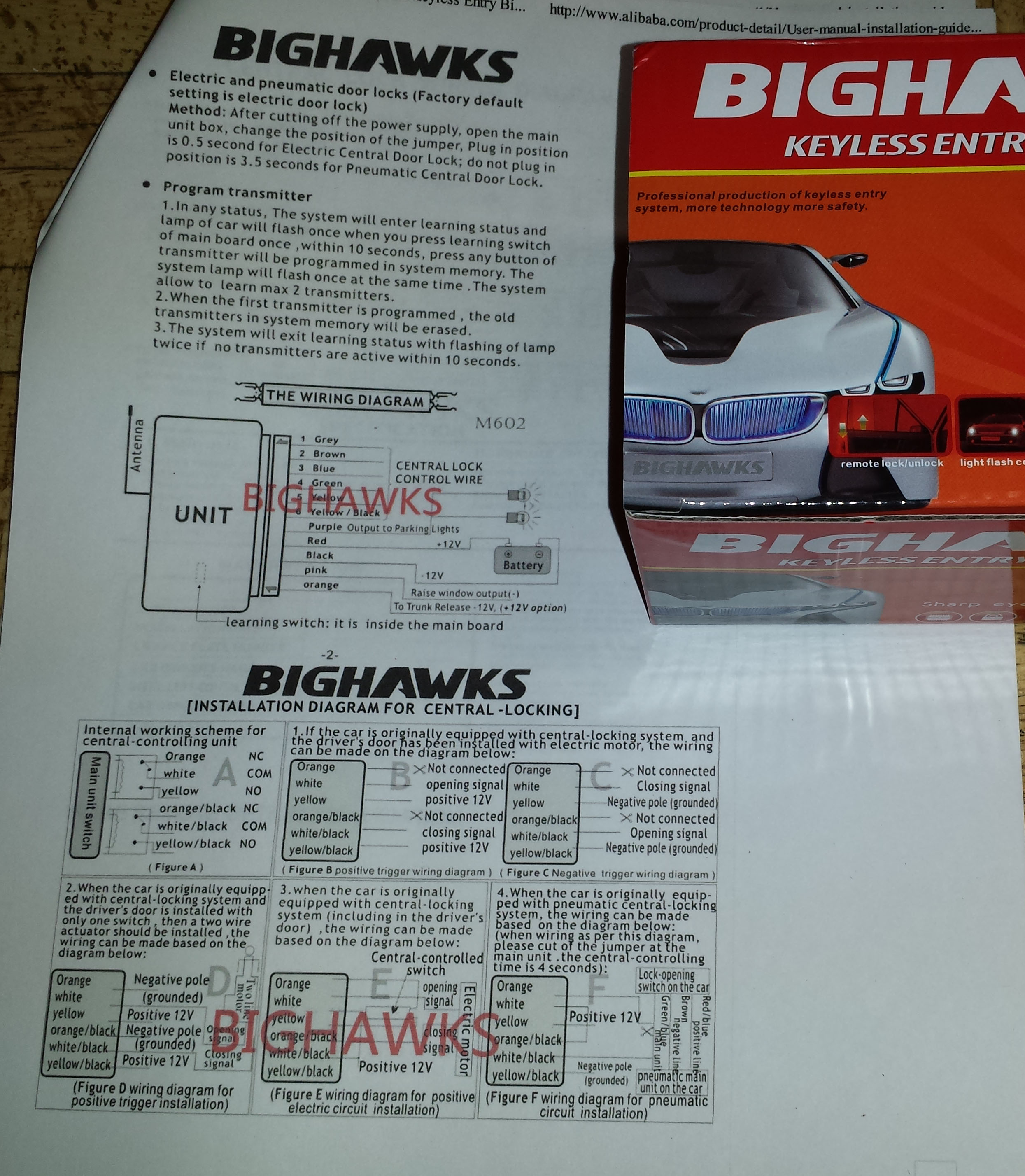
The BigHawks unit arrived with no instructions. I guess the Chinese vendors have learned it is cheaper and better controlled if the paperwork is offered sans paper. A quick search of the internet provided a page with the wiring diagram. I checked this information and found discrepancies right away. Some of it apparently applies to another model of keyless entry. The central locking relay configurations at the bottom of the page show wire colors used with my 4-button units of unknown brand and not the BigHawks unit which matches the colors named in the top of the page.
Despite the conflicting information, keyless entry with these improved fobs for $11 seemed well worth the effort to sort it out. Here is how the BigHawks unit got wired:

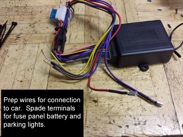
Basic connections: Battery and ground. Lock and unlock signal. Parking lights.
The yellow and brown wires get wrapped with the black ground wire to provide the ground reference for the normally open relay contacts which operate the lock and unlock functions in the 240. This bundle of three gets spliced into the black wire of the door harness.
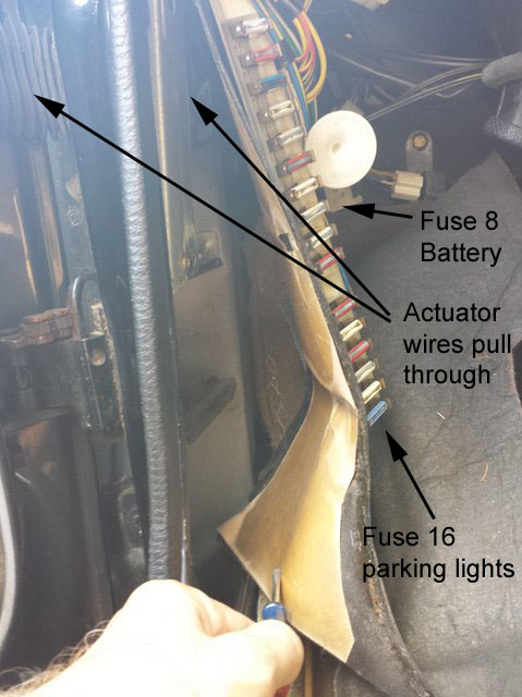
The red wire gets a terminal to plug on a tab of the fuse panel at fuse 8.
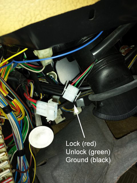
The blue wire splices into the 240's door harness red wire to operate the lock relay.
The yellow/black wire gets spliced into the green door harness wire to unlock.
Take the two purple wires (with the bulging diodes) together into a spade terminal to plug on a tab at fuse 15 or 16. I had a piggyback tab to use in case all were occupied, but did not need it.
Battery is most easily obtained from the load side terminal of fuse 8 on 240's having central locking. A female spade connector makes this a snap.
A bit beyond basic, most keyless entry units I've seen have an output to flash the parking lights. It is a means of visual feedback for the fob transmitter commands. In the 240, it is just too easy.
The one in today's example has two outputs for the same function, recognizing the European standard where left and right parking lights are separate circuits and may be isolated. The two outputs have steering, or isolation diode rectifiers in series to provide a battery positive to your parking lights separately. In US market 240s the left and right parking lamp circuits are tied together at the supply side of their separate fuses, #15 and 16 on the example 89 sedan (and I believe all 240s with central locking standard). In my US market 89 240 sedan I will put both of these wires from the unit into one spade terminal and push it on a spare tab for fuse 16.
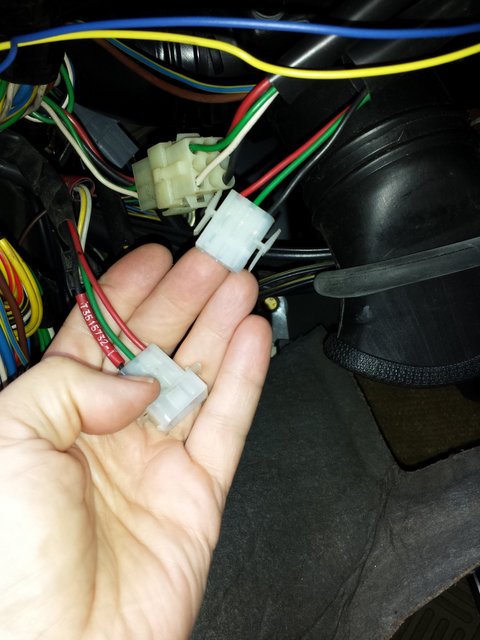
Ground, lock, and unlock are all three conveniently under the dash where the cabling leads to the door switches. Splice into the black, red, and green wires. Use a method you prefer, such as Scotchlocks, wire nuts, solder and tape, or shrink sleeving. For this interior application, I prefer the strip, split, and twist splice. In my experience as long as the splices remain free of mechanical strain and are insulated, these quick splices remain reliable.