Main Fuse for Engine Management Systems
Background - Symptoms - Diagnosis - Fixes
This is about solving what can be an elusive and intermittent electrical problem with the fuel and certain ignition systems in 240 Volvos built with Electronic Fuel Injection
Background:
1983 - 1990
Since 1983 and LH2.0, 240's with EFI through 1990 models have the fuel system (computer, fuel pumps, idle valve, injectors, air mass meter) all powered through the engine wiring harness (thick red wire) fused near the battery and originating at a battery junction box on the left inside fender wall. Every owner with that fuse has had reason to deal with it's holder and wiring at some time, mostly due to its being located right under the hood-fender gap, exposed to the elements.
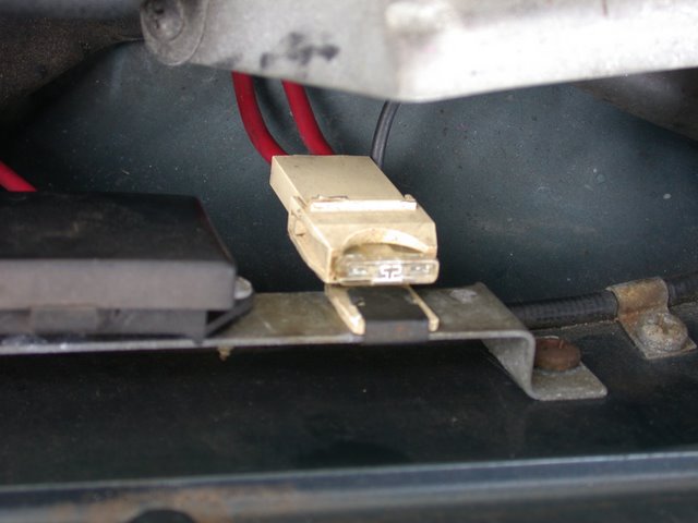
Wiring is vulnerable, terminals get loose, and a poorly executed prior repair may make it even more unreliable. Often the wire is found to be relocated to the battery terminal clamp screw with its exposure to acid. Before relocation, the smaller breakout from the positive battery cable fed the rest of the battery circuits using this bus in the battery distribution terminal box.
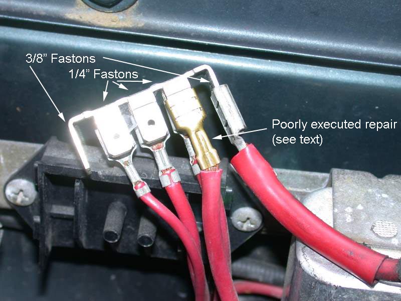
The common fix is to replace the original fuseholder with a new one, sometimes waterproof, but best of all, new and free of corrosion.
1991 - 1993
However, in 1991, the engine and main cabin harness underwent big changes, moving this fuse out of the weather being among them. And since 1989, with LH2.4/EZK, the ignition computer was added to the circuit, not that it greatly affected load, but it did add some complication to diagnosis. Now that these cars are all in their twenties, this new location is another kind of problem. It is exposed to the moisture from leaky windshields and water following the harness down to the lowest point - the fuse panel.
First, some misinformation circulates about the function of a fuse. A fuse does not protect the load. That fuse in the back of your radio is not there to protect your expensive electronics. It is there to protect the manufacturer from your lawsuit when the electronics malfunction and begin to request ten or fifteen times the normal amount of current, resulting in smoke and fire. Stated in the most basic terms, an electrical fuse is a fire prevention device.
A fuse needs to be as close to the source as possible to protect against the widest range of faults in wiring. A branching tree allows multiple circuits to be sized and fused separately and more remotely from the source, for example, the interior fuse panel allows shorter runs of smaller wire to lighter loads, or the fuses inside the plug of your Christmas tree lighting allow wiring in the tree to be rated at less than the 15A breaker in your entrance panel.
The construction of a fuse must be chosen to use some energy in normal operation, so that it can heat enough to melt when operation becomes abnormal. A 16A fuse must be strong enough to reliably pass that current but weak enough to melt its metal when 16-amp wiring becomes hot enough to melt its insulation.
Making connection to a fuse has always been a challenge to designers. It is a trade-off between ease of replacement by the user and contact force. Mechanical contact force and its resuting low electrical resistance is especially important in low voltage -- less than 100 volts -- circuits, where an invisible layer of oxidation may survive the low electric force.
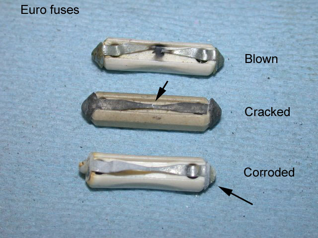
The quickly replaceable Bosch (ATS, GBC, DIN 72581/1) fuse populating the interior fuse panel depends on the springy brass of the holder to keep a contact force high enough to exclude oxidation from invading the contact area. Any moisture, and galvanic corrosion makes the choice of zinc/tin in the one-piece fuse element yet more susceptible to poor connections in our copper alloy panels.
The ATO/ATC style fuse is not quite as easy to remove and insert. Most holders use similar metal contacts, although I'm sure many of you would immediately think of the 700 series ashtray fuse panel as an argument against saying the blade fuse is the answer. Even the PAL fuses, with their wide contacts to increase surface area will have problems maintaining low contact resistance which is a special requirement of low voltage circuitry as compared to the sort of self-maintaining environment above 100 volts.
While the fuse was reliable in the 90's, invisible corrosion, or even the visible galvanic corrosion from dissimilar metal contact, mean trouble after years pass. I've had some good results simply cleaning and retensioning the fuse contacts and then using a fuse with a copper or brass element. Neither the nickel plated glass version of the Eurofuse or the tin/antimony elements in ceramic or thermoplastic prevent this galvanic corrosion with the brass fuse panel contacts. In fact the two 91 cars in my family have not suffered any of the symptoms I attribute to this problem since moving to copper fuses, but a thread in a Volvo help forum made it clear to me this is not an isolated event.
1993
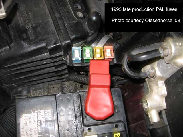
Late production 1993, the last of the 240's came with PAL fuses mounted to the positive battery terminal. Could be Volvo recognized the problem with fuse 6 this early, as they abandoned it for the return to the correct side of the firewall in several circuits. A fuse is needed for fire protection. It doesn't protect "expensive electronic components" but guards against more common mishaps like insulation pinched or rubbed through. For that purpose it belongs as close to the circuit's origination as possible. My guess is the battery-mounted fuse array change had more to do with product liability than the failings of the old Eurofuses in the interior panel. I don't own one of these, but I've seen pictures of overheated contacts in this final location Volvo chose.
Symptoms:
Beginning in 1989, 240's have the early On Board Diagnostics version 1 (OBD-I) to confuse us and frustrate us with diagnostic codes translated to "rich or lean at part load" among other vague reports. Probably one of the most reliable indications given, pointing to a problem with this fuse, is the absence of fault codes (1-1-1) on both fuel and ignition computers, coupled with intermittent driveability problems like hard starting, tendency to stall, and poor fuel economy.
If power is interrupted to either computer (protected by fuse 6 in these 1991-1993 cars) the computer memory is instantly wiped of fault codes and learned adjustments to trim. So OBD tells me 111 (all is OK) and the car drives poorly while the adaptive trim adjustments get re-learned over the first ten miles or so. Of course, there could be other causes of the same symptoms, but likelihood suggests checking the integrity of the power delivered along this circuit. If the fuse contact has obviously overheated, I have my conviction.
Diagnosis:
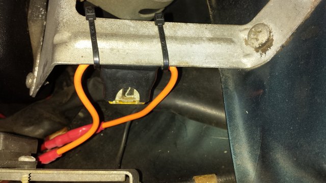
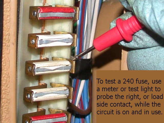
In the 83-93 cars with EFI, there's a simple test to be made if corrosion at the fuse is suspect. When the key is in KP-II (ignition on) the main relay (or system relay, part of the two-relay FI relay 85-93) passes fused battery to the air mass meter (AMM or MAF). This component, along with the fuel computer, idle valve and injection provides a load through the fuse. To see if that load is being supplied full battery, measure the power delivered at the AMM connector by peeling back the boot and checking power at orange wire (red/black on 92/93).
This is what I decided to do to improve the reliability of that circuit in one of our 1991 cars, as the opportunity came up during its latest maintenance.
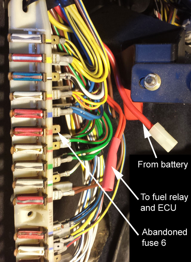
Of course there are other possible causes resulting in intermittent and unreliable power reaching the engine management system components. In the 1991 version of the wiring harness, a 6.0 mm sq. red lead between fuse 6 and the battery junction box is dedicated to this system. Leaving fuse 6 it is split into two 2.5 mm sq. red wires so two cabin-to-engine harness connector pins can share this circuit's current. Common reasons for engine management power faults arise at this 12-pin connector, the crimps and tab tightness in the 1/4" spade terminals at the battery junction box and fuse panel. Also, terminals in the fuel injection relay socket, the solder joints inside the fuel injection relay, and ground returns at the fuel rail mounting screws are well known to experienced owners of these cars.
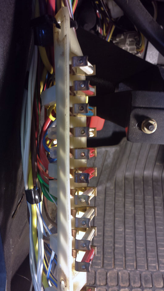
Here I have the fuse panel loose so you can see the evidence fuse 6 got hot.
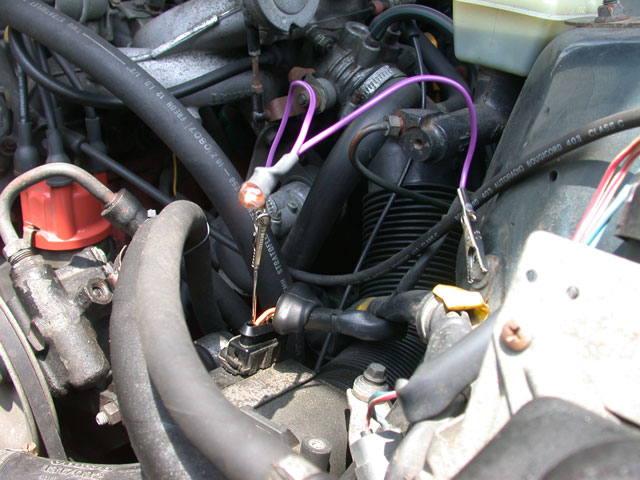
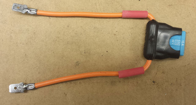
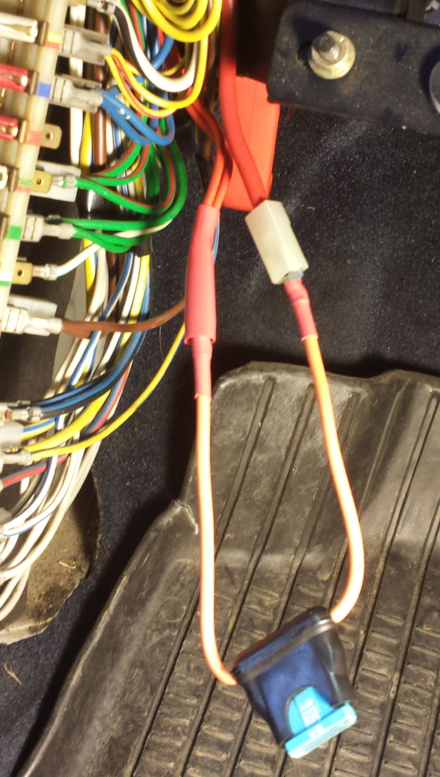
This is a fuseholder for blade fuses much like those we've installed in our older Volvos to replace the one under the hood. I've attached some uninsulated male spade connectors. I crimped them, because I have the correct tool, but lacking it, I would have soldered them. I did not forget to insulate.
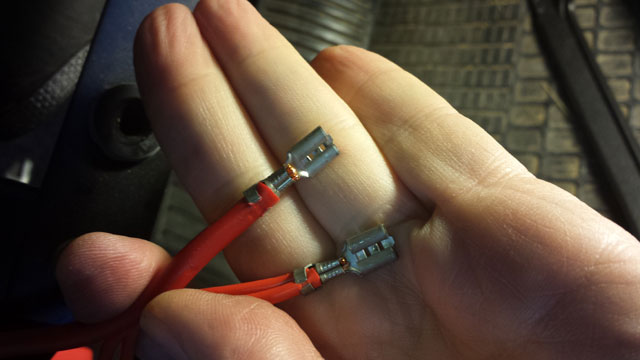
Here, I've removed the harness wires from the fuse panel tabs for fuse 6. On the '91, the feed for fuse 6 is a separate line from the battery box, and not shared with the other fuses, so piggy-backing to an unused tab was not one of my options. I am making sure the factory crimps are still tight and do not exhibit any evidence of overheating. I gave them a squeeze to ensure they had contact force with the male tabs.
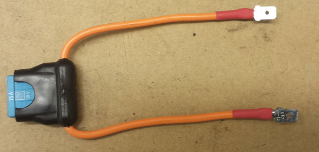
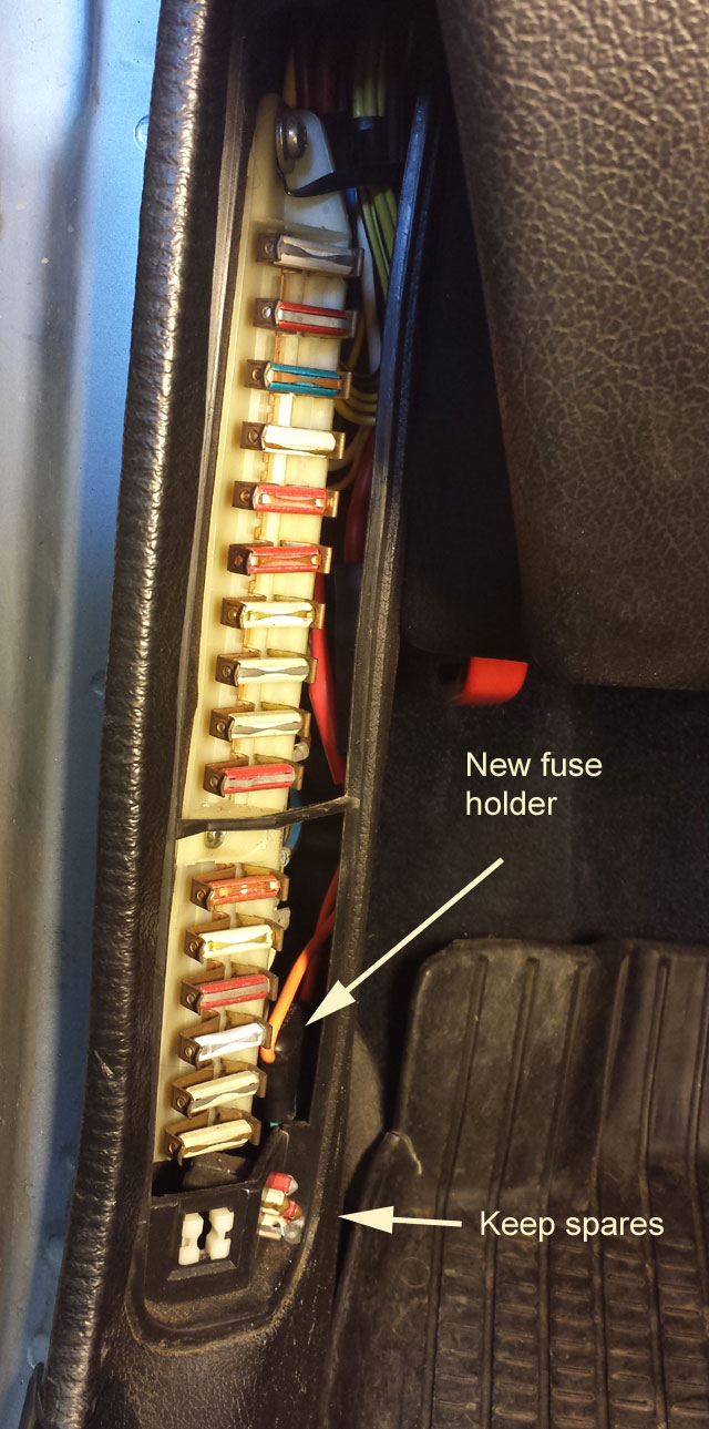
I carefully insulated the assembled connectors and tucked the new fuse holder along side the panel, leaving fuse 6 as nothing more than a spare.
Return to links index