Here’s what mine looks like:
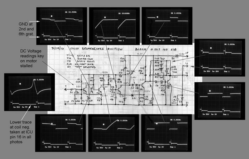
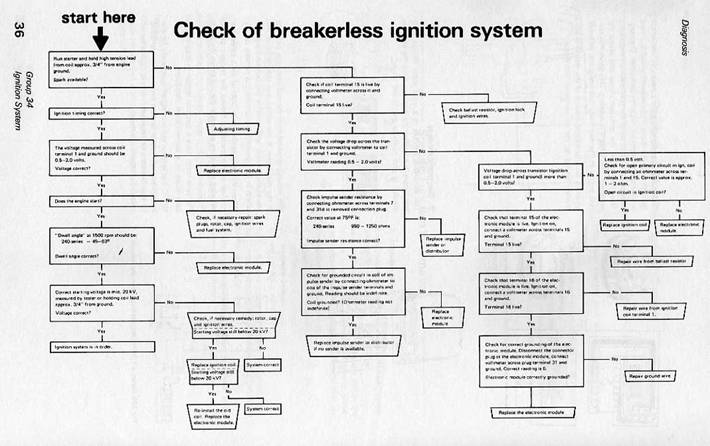
If your browser won’t zoom this to legibility, a full resolution pdf is here: http://cleanflametrap.com/ignDwg01.pdf
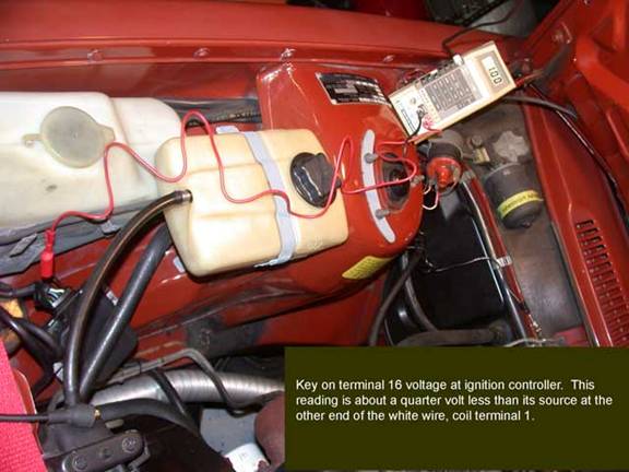
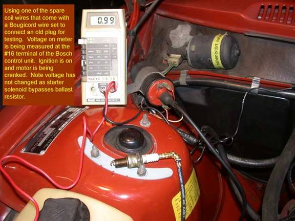
Here’s how it is connected in the car. Fuel injection senses ignition at terminal 1 (white/red wire) to control fuel delivery. The starter solenoid has a contact to bypass the ballast resistor during cranking:

Some further measurements on the 0221 122 006 coils from three cars using this ignition:
83 244ti – in garage at 50° F : Coil primary 1.5 ohms, secondary 10K
79 244 – in garage at 50° F: 1.6, 9K
83 242ti – under hood warmed by morning sun: 1.9, 12K
Spec in green book is 1.9±0.1 primary, and 9.5K ± 1.5K secondary (not temp given)
I don’t give the variation in these readings much significance and expect it with temperature, and don’t pretend I can achieve even 2 significant digits measuring low ohms.
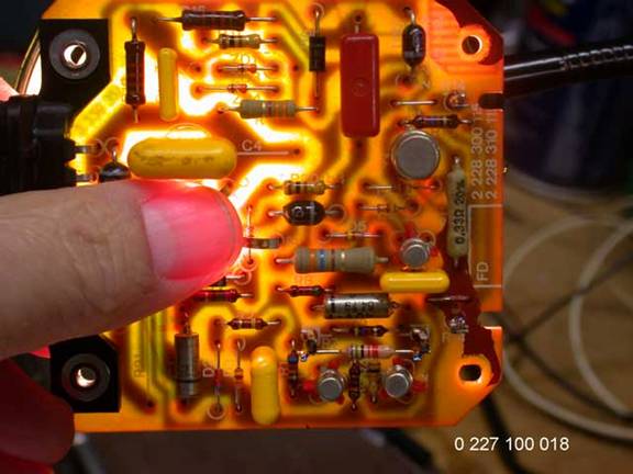
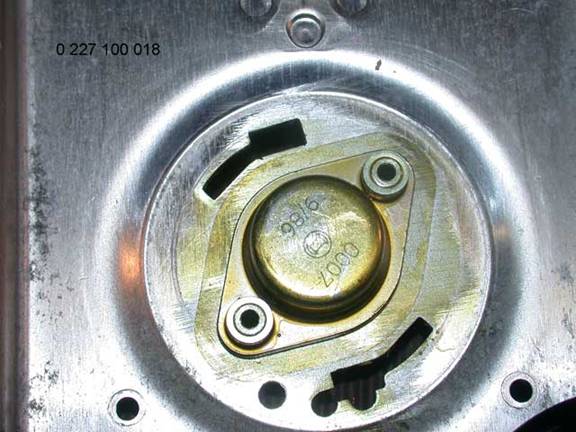
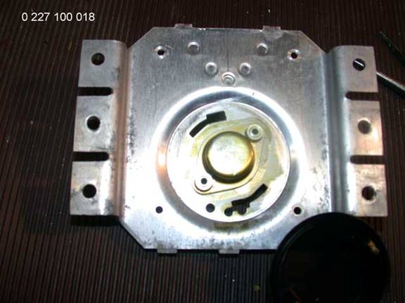
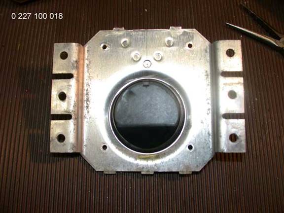
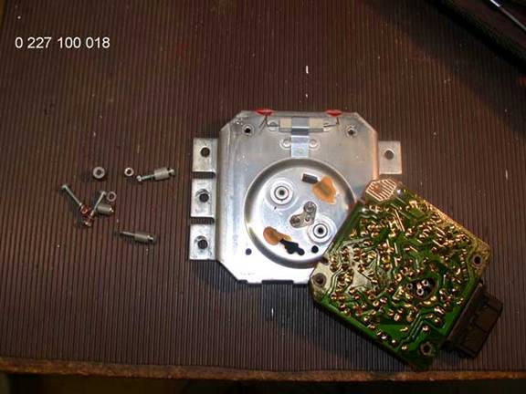
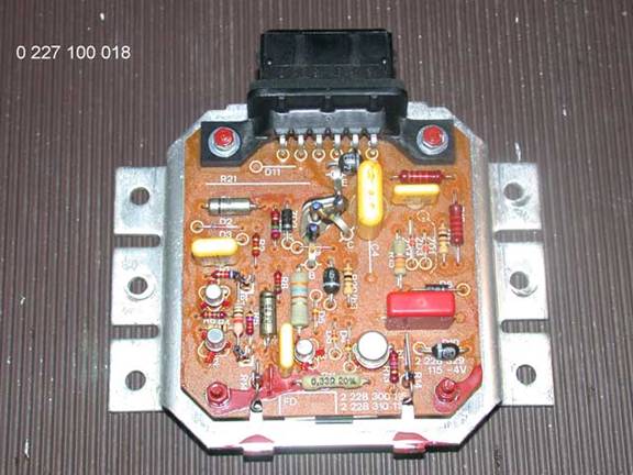
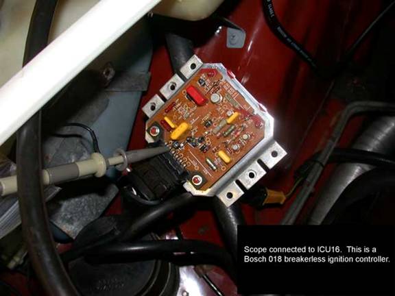
Here are some views of the ignition control unit:
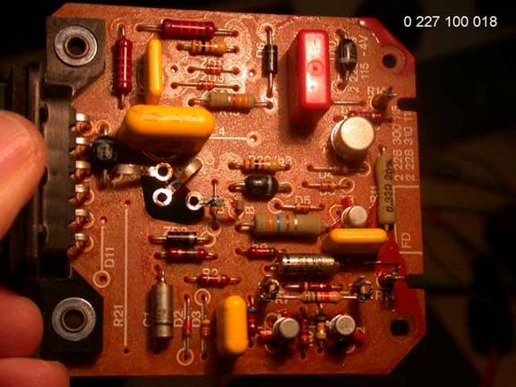
Here is R14 – clamped to the heat sink:
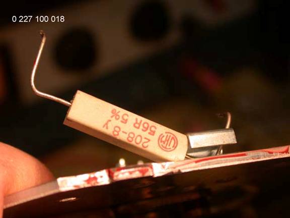
Bosch special…
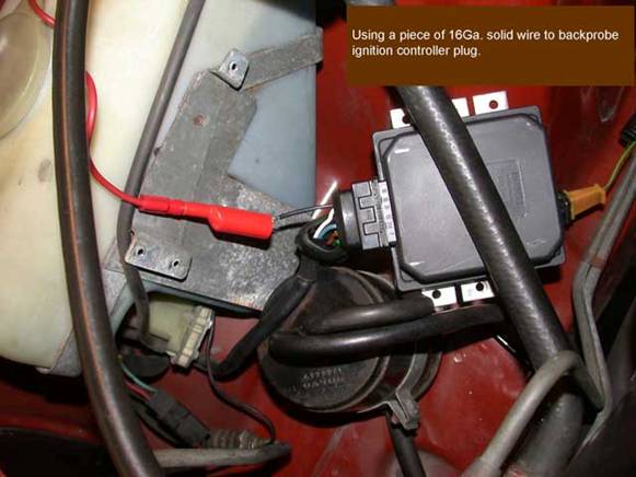
This approach to probing the circuit got me into
trouble. The 16
I think you shouldn’t leave the coil tower without a wire in it when operating the ignition. It arcs easily to either primary terminal.
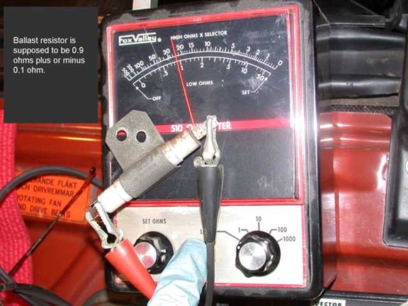
Measuring low ohms is not as easy as connecting your DMM and subtracting the lead resistance. This bridge type meter is accurate only after balancing it and cleaning (wiggling) the connections to the device under test. A new resistor of known precision, and value near what is being measured, serves as a standard to verify your measuring technique.
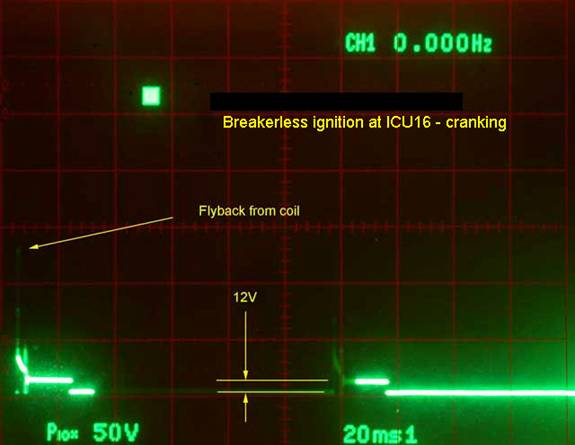
Connecting a scope to the ignition coil circuit is easy with the top off. When the coil collapses, the trace is off the screen (eye can see it, but camera doesn’t pick it up) at highest attenuation and X10 probe, so I’m leery of cranking it up to damage the scope’s input circuitry. I don’t have an ignition scope.
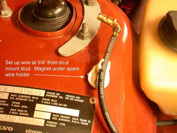
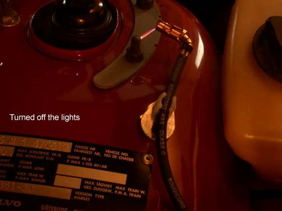
The troubleshooting guide in the 1980 manuals declared a three-quarter inch spark to be indicative of the 20 kV expected from this ignition system.